Archive for the Category RC Aircraft


Setting Wing Incidences

Here is the Gieco Caveman style How-To on setting wing incidences. This is step #22 in the Carden manual for the 35% 260. This step gets about 1/4 of a page. Its not complicated or hard but it is something you have to plan out.

I’m going to assume that were starting with the wing tube socket installed (step #21) and the wings are done with the leading and trailing edge stock installed and sanded to shape.

First we are going to do all of the drilling that we can on a drill press. Drill 4 of the square mount pads and all 4 of the rectangular mounting brackets dead center with a hole sized to the diameter of the bolt your going to use. Carden suggests using 8-32, I’m using 4mm. With the remaining 4 square pads drill a hole for the blind nut, again dead center.

IMG_0864 (by gareth.ky)IMG_0866 (by gareth.ky)IMG_0871 (by gareth.ky)

On two of those pads add an additional hole clear of the blind nut. This is the setup pin hole. The setup pin will keep the wings level when the anti-rotation bolts are removed. This is handy while you look around for your socket driver at the field. Its just an affordance for setup & tear-down and not a load bearing part.

IMG_0874 (by gareth.ky)

Next find the root cap stock with the pre-drilled socket tube holes in it. Mark the center line of the plank and then transfer the locations of the mounting pads to the center line. Use one of the pads and a square to mark the locations of the pads. Cut these out inside the lines. Sand until the pads are a snug fit.

IMG_0876 (by gareth.ky)

Install the blind nuts in the wing pads. Place the pads into the root cap holes you just cut. The setup pin hole should be pointing towards the tail. Tack glue the pads with some CA. I just did the 4 corners. I’m using polyurethane glue to install the root cap so it will make a good bond later on. Cut the root cap stock in half to make two root caps.

IMG_0877 (by gareth.ky)

For each wing we need to glue in the wing root cap. To do you have to cut away some of the foam so that the pads are recessed into the wing root. To do this I just fir the root cap over the socket tube and line it up with the center of the airfoil using the center line I drew earlier. Once its aligned I press the pads into the foam so it leaves a mark. Using a Dremel router I cut a deep pocket behind the blind nut so that no glue could enter the back of the nut. Then I set the router to cut the depth of recess needed for the pad and cut out the shape of the square mount pads. Test fit again and it should be good to go. Sand down the tube socket so that its flush with the root cap or even slightly inset.

IMG_0879 (by gareth.ky)IMG_0881 (by gareth.ky)IMG_0882 (by gareth.ky)

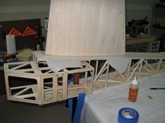
Now to get a good fit between the wing root and the fuse sides. I think I saw this on FG somewhere else and it didn’t look like it could hurt. Flip the fuse on its side, put the wing tube through the fuse and mount one of the wings on top. I use polyurethane glue to attach the root cap. Make sure to get adequate glue around the ply mounting pads. Glue is going to come through the seams where the mounting pads are so put some parchment paper between the fuse and the wing to keep it from sticking. The glue takes 2 hours to set up so this step takes a while. You may want to label the wings left & right at this time because its hard to tell which is which after the root cap is on.

IMG_0888 (by gareth.ky) IMG_0894IMG_0893 (by gareth.ky)

Resist the urge to trim the root caps, all that extra material is going to come in handy. So now its time to set the incidences. Use a good digital level and an incidence tool. Make sure your table is flat and level. Mount both wings on the fuse with the fuse flat on the table and upside down. Make sure that you got the right wing on the right side of the aircraft and that its underside is facing up. Use the incidence tool to find 0.0 incidence. Use a block of scrap balsa and some push pins to secure the wing in this position. Make sure at least one of the pins goes through the 3/8 square stock in the fuse sides. The soft balsa on the fuse sides is too flimsy to hold the wing and keep it from slipping. Take you hands off everything and verify the level still reads 0. Set both wings this way. The blocks will allow us to move the wing and find 0 incidence again consistently.

IMG_0897 (by gareth.ky)IMG_0902 (by gareth.ky)

Now we have to find the locations of those blind nuts so we can bore a hole in the fuse side to match up with it. I have seen various methods suggested using tape or sharpened screws. This way is easier and, IMHO, more accurate. Use a pin to probe for the hole from inside the fuse. Don’t worry, the pin cant go through the ply block in the wing root so it can’t make big holes in the exterior of the fuse sides. Just the tip goes through the balsa, not the whole thing. The holes on the inside get covered up later. Once you strike pay dirt poke more holes all around to find the extent of the blind nut hole. This will help you see the center when you pull the wings off.

IMG_0899 (by gareth.ky)IMG_0915 (by gareth.ky)

Pull the wings off and you should see spots on the fuse sides peppered with holes. Open up the center of each area with a pin or small drill bit. Make a sand paper drill from 220 grit paper and drill the holes but twirling it. Open up the hole until its the size of the perforated area. Slide the wings back on and check that all the blind nuts are accessible. You should also make holes for the setup pins at this time.

IMG_0916 (by gareth.ky) IMG_0903 (by gareth.ky)IMG_0917 (by gareth.ky) IMG_0908 (by gareth.ky)

Now we glue the 4 remaining mounting pads to the inside of the fuse. The is the *critical* step. Once they are glued in the incidence of the wing is set and you cant change it. I do one wing at a time so I can have the incidence meter to make sure the wing is at 0. Use 30 minute epoxy, not poly glue, for this step. The poly glue could expand and seize the bolt. Put the epoxy on the back of the pads and screw them in place. Do not tighten the bolts down, just snug them. Check once again that the wing reads 0, it might shift when the bolts go in but I didn’t have this problem. Then just walk away. Wait till the epoxy has cured before moving anything.

IMG_0920 (by gareth.ky)IMG_0927 (by gareth.ky)

Now its time to mount the setup pin. Make the pin about 3 inches long and use poly glue to install it in the wing. You only need it to stick out about 3/8″. If you leave it a little bit longer you can sand it down so its flush with the mount pad inside the fuse when the wing is installed. You may want to harden up the balsa around the setup pin opening with some thin CA. You’ll have to drill a hole in the mounting pad in the fuse side to match up with the pin. I strongly suggest doing this on a drill press. I tried it with a hand drill but the wood tends to ‘climb’ up the drill and mess things up. The drill press took more time but the result was much cleaner.

IMG_0930 (by gareth.ky)IMG_0931 (by gareth.ky)

Last step, add the balsa spacer and the retention bands. This is pretty easy, just glue the parts in place. You’ll probably have to sand and shape the two forward bands to fit. Again I used 30 min epoxy so it didn’t get into the bolts.

This is the after shot, both wings still read 0.0 degrees. There is not slop or wobble at all. The bolts fit but are very snug and its a bit of a challenge to get them engaged properly. I’m going to put a few flight on the airplane and see if things sort of shake/wear into position. I don’t want to mess up a good things with sand paper just yet.

IMG_0936 (by gareth.ky)

n00bs Gonna Build a Carden

I have been planning this for a over a year. Lurking on The Flying Giants and other sites getting ideas and learning. Last week I moved out of my old 1 bedroom apartment into a new house which means I finally have space to start this project. I’ll be building a 35% Carden Extra 260. So far only the kit has been purchased but I have some clear ideas on how it will be built and whats going into it. This will be my IMAC machine for 08/09 and I’ll be starting in Sportsman.

So some background on my experience is in order. When I was 13 I built a 6 foot span Spectra motor glider that I never flew. Before that I was building stick and tissue free flight models. Then there was a long hiatus fro the hobby for high school and college. I finally learned to fly in March of ’06. More recently I built an O2 electric profile and I have designed and built several of my own foamies. I have never built a giant scale airplane. I have about 5 mins of stick time on other peoples giant scale airplanes (Air McNair’s 35% comp arf 330 & Dan Bierlys 40% Wild Hare extra 300). I have never worked with foam cores before or painted fiberglass or used a scroll saw. I have never even started a gas airplane engine. So I’m a Giants n00b and this thread is going to be from that perspective. Its probably going to go into more detail than most build threads out there because its all new to me. The build will be shown in all its ugly duckling stages and any “oops” moments will be posted here.

It was hard to choose which airplane to build. I picked the Carden because I really like the looks of the airplane over the other 260 kits out there. I would have prefered to build a 300 but at this time no 35% 300 kits are out here. I couldn’t imagine spending this amount of time on an airframe that I personally didn’t like the looks of. Its a personal choice and it has consequences. This is more involved than say a Dalton where everything is laser cut for you. I wont be cutting any corners, I want a light, straight, contest grade airplane. Building is a hobby and flying is a sport. I’m as much a fan of building as I am of flying so there was no question, I was going to build from sticks.

The first step for me is setting up a flat straight build table. In fact I need two tables, one for tools and one for the building/layup work. The tables are going to be built based on a design I found linked from FlyingGiants. The build table is long and narrow, topped with a solid core door. The workbench is topped with some 3′x4′ ply that come pre cut from the hardware store.

Building Tables

I found a door at the Home Depot for $42, solid core, 30×80. I went for the cheapest and narrowest door I could find. I rented the miter saw for the project and ended up needing it for two days to get finished. You kind of have to cut as you go as not everything is going to be cut exactly right. After the first table was finished I discovered that the saw wasn’t square, it probably had 1-2 degrees of bevel. Make sure you square your saw before you start. I got the work table and all the legs for the build table done in one day. I had to make a couple of extra trips out for 2×4′s. The second trip the wood I got was softer than the first batch and that just sucked. I ended up throwing away 3 pieces and going back to Home Depot for more wood. The design is really solid and the 33 inch hight is sort of magic. Its tall enough for standing and short enough to sit at.

IMG_0360 IMG_0364 First Table Finished Build Table
There is an associated build thread over on The Flying Giants and a flickr photo set to accompany this build. I will try and post about once a week with progress.

Drawing Foamies in Sketchup: Tips & Tricks

Bet you thought I was gonna write about snow. It was cold, I’m over it.

I have been putting some serious time into Sketchup for a new project. Since nobody on RC Groups reads this blog I think I can get away with posting pics of it here as examples before I mention it over there. Ok, on with the tips:

Make components of everything symmetrical. I do half the wing, half the elevator, half of the sides etc. Don’t duplicate anything, just make a component and copy it. Here you can see a shot of the new project and what you see is exactly 1 of each component in the drawing. This is the best way to cut down on your workload.

One of Each Component

If something would be more convenient as a whole object, say a whole wing or the elevator use make a group out of them. This way they can be selected and manipulated as if they were one component without the duplicated geometry penalty. The Outliner is your friend here. You can rename groups and rearrange the group hierarchy in the outliner.

Sketchup makes it really easy to extrude things into 3D. Resist the temptation to make all your parts 3D. In the long run its just so much easier to manipulate things in a 2D plane than in 3D. It will save you a lot of work. You can place everything in 3D of course but you have to remember to keep things the right distance apart (3mm or 6mm depending on the depron or foam thickness your shooting for). You run into so many problems making geometry changes in 3D that its just safer to keep everything in 2D. If you have something complicated that would be easier to work out if everything were in 3d try making a copy of all the components and use the “Make Unique” option so your changes wont affect anything else. Usually you can work it out in 3D and then copy the changes back to the 2D parts.

Outliner

If stuff suddenly stops forming nice surfaces its because all the points are not in a plane. Finding the offending point or points can be hard. A quick trick to see which points are off the plane is to use the scale tool on the component. If the scale tool even lets you stretch the component vertically its not a flat surface. Stretch it vertically and the high points will be exaggerated and you can find them easily. Here is an example where one of the circles is 0.1mm higher than the rest. Hard to see but with the scale tool its easy.

Use Scale Tool to Find Points Not On A Plane

Don’t embed cut out marks in your components treat them like an overlay instead. It took me a while to grok why this is important. At first I was applying lightening holes and assembly cutouts right to the component geometry. This had lots of undesirable effects, It broke up the geometry and making changes was very involved. Now I apply cutouts as an overlay using a separate component. Then I group the cutouts and the main component together. Now I can play with changing the construction cutouts without affecting the component geometry. Also things like lightening holes that are supposed to be very similar can be a single replicated component. You can even lay them down with the move/copy tool. Another bonus us that scaling now works correctly. If you have a 3mm cutout in your component is probably a hard value that you don’t want to scale if you scale the component. Just extract all of that stuff out into a separate component and it wont scale. This is great for shrinking or stretching plans.

I gave up on doing tiled plans. Sketchup doesn’t support it natively and there is no good solution that I have seen yet. You can print plans at Kinkos on the large format printer and save yourself the trouble. The large format black and white printer will print up to 36″ or 90cm wide by however long you need, It’s a drum fed laser. An F3P model will cost you between $8 and $10 depending on how well you use the space. If Sketchup suddenly supports this i may reconsider but having the plans printed is very convenient.

Plan Layouts

Lastly get Bezier.rb before you get too involved in doing any curves. When its correctly activated you’ll find it in the menu; Draw ->Bezier Curves. This is the secret to nice bubble canopies and the other tricky curvy bits. Its a must have. I just wish it was in there from the beginning and it had an icon in the toolbox. Just assign it a hot key (I made mine ‘C’ since its rare that I draw a circle).

My biggest Sketchup time saver? The Spacebar is the default shortcut to get back to selection mode from whatever tool you using.

Look for plans of the new airplane as soon as I get one built and tested. At the rate I’m getting things built and flown it might not be till late January.

5 Ways to Sell More Kits

I just been through the process of looking for a kit to build this winter. Its just hard to believe how little choice there is in the market for kits these days. I have been away from the hobby for 12 years. Back then few airplanes were ARF’s, now few airplanes are kits. Its an understandable transition, people don’t have time/space/expertise to build a model. Still I think that perhaps 10%-20% of the total market would like to build kits. For us its not about the convenience of the ARF. We are makers, we enjoy creating things.

So in the hope that there will be more kits on the market in the future and more people building kits I put together some suggestions for the people who make the kits to help them sell a few more. This isn’t meant to get down on anyone or get negative. I’m sure anyone still making kits is in it for the love of the hobby. I know there cant be a lot of money in it.

5 Ways to Sell More Kits

  1. Offer kits that people want to FLY and build. This should be the obvious part but its not happening. Example: Yak’s are hugely popular but there isn’t a single 50cc Yak kit on the market this winter. Update your kits with interlocking parts and prefabrication. Its not enough that you convert and old design to laser cutting, the parts need to interlock to make building easier. Doing menial tasks like beveling hinge lines are boring and take a lot of time. Prefabrication by machine saves build time and gets better results than many can archive on their own.
  2. Offer complete kits. Or offer a complete, super high quality hardware package to complement a builders kit. Complete kits included EVERYTHING an ARF airplane would have had. This helps with estimating costs for the builder. A complete kit with hardware shouldn’t cost any more than a similar ARF (why should it?). With an ARF the costs are clear; with a Kit its hard to estimate what the project will ultimately cost. A key kit selling point is that you can get higher quality hardware than an ARF. Offer what you would want on your personal airplane.
  3. Provide manuals online. Preferable in HTML with high resolution photos. This lets the builder see what they are in for before they buy the kit. It helps them feel confident that they can complete the project. Update the manuals as needed, HTML is easy to update. HTML manuals can be linked to in a build thread and the images can be more detailed and helpful than the smaller images in a PDF.
  4. Provide help with Finishing. For the new generation of ARF buyers that have never built a kit the most difficult part is finishing. Have an ‘official’ color scheme and publish templates for cutting the covering. Provide some Vinyl Graphics (great free advertising!) with every kit. There is general lack of good covering and painting information out there right now that needs to be addressed.
  5. Leverage the community. Encourage builders with a variety of skill levels to build your kits and post build threads online. If someone wants to do a build thread get involved and support their efforts. Accept constructive criticism and learn from their mistakes to improve your product. A good build thread can be better than the manual that came with the kit. Link to good build threads from your website.

I wish I was building an MX2 this winter but I may have to wait a few more years before kits of that airplane get produced.