260 Build Update #3

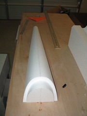
On with the Sheeting. I did the Belly Pan, Hatch, both H-Stabs, Rudder and Turtle Deck in that order. Then I got help from Dan to do the wings.
I used the method I like best for spreading the glue is a small foam roller that you can get at Walmart. This really gets a nice thin layer of glue evenly all over the sheet. Just keep rolling until the sheet turns a uniform color and you don’t see any big globs of glue left on it. For the wings I think I used 6oz of glue and at least 1oz of that is waste that ends up in the roller. So at most there is 1.25oz of glue on each skin. Each wings had at least 400lbs on it.

I put parchment paper between the shucks and the skins. The upside of this is glue can’t get through the skins. The downside is the parts tend to move around very freely until the weight is applied. Take some care and time to align the part with the shucks so its sits square. I used about 300 pounds of weight on all of the other parts in the form of various concrete blocks I got for a few cents each at Home Depot. Even with all that I didn’t get good adhesion around the edges of some parts. I guess the gap between the shuck and the part was just wider there.
You want to take some care with the rudder sheeting alignment. I just joined the Fin and Rudder sheeting parts with masking tape over the plans so that they covered up the whole rudder. Put the foam over the plan and make some reference marks so you know approximately where you want the sheeting to lay down. Try and get the seam to run through the area that will be cut out for the hinge line. Don’t do anything stupid when cutting off the excess sheeting. Use a sharp blade and then a sanding block to make it smooth. I chipped some parts with a dull blade and I’m regretting it now. A hobby saw works well for the curves.
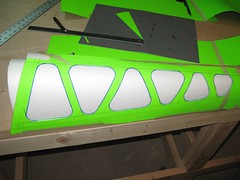
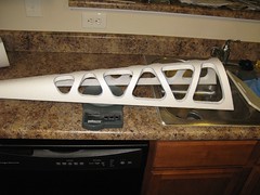
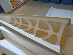
So I’m sure you can see the holes in some of the parts. The hatch, belly pan and turtle deck are all cosmetic parts. They don’t contribute much in the way of strength to the model. So they make great targets for lightning. I’m going to guess that I saved about 5oz off the airframe and much of that is from behind of the CG. This technique leaves the part fully sheeted so its easy to cover but it avoids large chunks of foam and the glue that goes with it. Here is the HowTo:


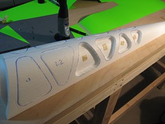
Mark a reference line down the center of the part and the center of the sheeting.

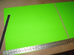
Make a template of the boundaries of 1/2 of the part.

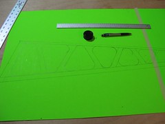
Draw your cutouts on the template and cut them out. Be smart, do triangles or cut in the same direction as the surface curvature.


Place the template on the reference line and mark the cutouts. Flip and repeat for the other side.


Cut out the foam with a Dremel router or hot wire tool. IMPORTANT: Keep the tool perpendicular to the surface. Put cutouts back into place with a loop of tape.


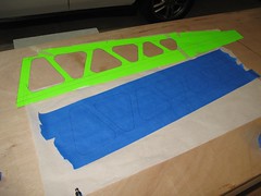
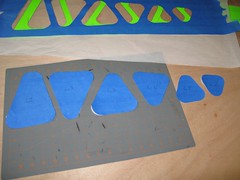
Place overlapping strips of masking tape on parchment paper and cut out shapes.


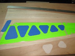
Use the template to position the cut out tape over the part.


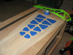
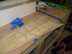
Then just spread glue as normal, peel off the tape and carefully align the foam part with the reference mark on the skin. Set up the part in the shuck as normal. When the glue dries you will have to pull out the routed foam pieces, none of mine stuck to the wood.

    I tried a few different procedures on the hatch and belly pan. The above steps are more involved but the result is the best. The turtle deck isn’t trimmed yet and it weighs 2.5oz (72g). 20g of foam was removed. I don’t know how much I saved on glue because I had to work fast and didn’t get the parts on the scale.

    Carden 260 Build Update #2

    This weekend I took on step #1 from the manual, make the skins for all the foam parts. I gotta say this is one of the more mind numbing and labor intensive parts of the build. There is a technique you need to follow to get good results. The quality of this work will eventually play out in the covering so its best not to cut corners.
    The sheeting in the kit comes “edge trued”. This means that the long edges of each sheet should be a mathematically perfect straight line. The lines don’t have to be parallel, just straight. As it was I found that just about every sheet in the kit had was slightly bulged in the middle. Sometimes its ok to just bend the sheet and hold it in place with masking tape. Most of the time you should sand the edge to make it straighter. I say should because you don’t have to, you could just fill the gap with glue. Of course I’m some sort of perfectionist so I had to go and true the edges myself.

    Walt(ref) has a fancy rig(ref) to true his sheeting. I didn’t have one so I improvised. The edge of the door that tops my workbench is very straight. I just moved the sheet to the edge and held it down with my large ruler. Then I took a 12″ T-Bar sander and sanded it square against the door. You wont have to take off much, the sheets are already 90% there.

    I used a gram scale to weight all the pieces and split them up into piles of lite, medium and heavy. On the flight surfaces I put the heavy wood over the wing tube area and the light wood towards the front and back of the panel. On the other panels the wood has already been sorted and cut so you don’t really have any decisions to make about how to use the wood.

    Once you trial fit the sheets and don’t see any big gaps its time to tape the seams together with 3/4″ masking tape. Here is the first bit of technique: rub the tape in hard so glue can’t get under it. On the first wing skin I didn’t press hard enough and got a lot of extra glue under the tape. the rest of them I really got it stuck down and the glue cant go anywhere. Once the skin is taped together its time to glue the seams. What worked best for me was to work 3 seams at a time. Apply the glue, remove the excess and then tape across all three seams. This makes for faster work and fewer pesky bits of tape to remove when its all done.

    To apply the glue you are going to need some sort of syringe type device with a fine tip. I went to the local Walgreens and asked the pharmacist if they had any syringes and got a freebie! It came without a tip thought so I had to make something up. I cut the end off a dropper that I had for applying CA, I get them at my LHS. If you cant find these then the CA tips available at Hobby-Lobby on online may also work. Either way plan on having this tool before you get started. Even blunt tipped syringes cant be had at a drug store in the USA.

    Once each panel is complete I found that it wanted to curl up due to the tension in the tape. Just flip it back over so the side with the seams taped is on top. I used books to hold the panel flat as it dried. I knew I would need that calculus book for something! I left each panel under the weight for about an hour. They come out very flat and uniform, much more so that some pics I have seen of other builds online, so I think I’m on the right track. I did some of the smaller skins first to get the hang of it and they went pretty well. I was using an old credit card to scrape off the glue and I didn’t realize that it had some bumps on it. This put some long scratches in the skins. I switched to a different tool, a soft silicone spatula, for removing the excess glue and this worked much better.

    I had a couple of screw ups this week. The instructions show the rudder and fin (v-stab) coming out of some 48″ planks with some scrap on the end. the instructions even list these planks on the materials list. Last week I used some of the “scrap” off the end of a 48″ plank as end caps for the wing tube sockets. Turns out that the only 48″ planks packed in this kit are for the wings. The other bits come pre cut in bundles and that “scrap” isn’t in the kit. Luckily i didnt cut very much off the end so I was able to use the piece for the leading edge of two of the wing panels, cut diagonally.

    I also managed to screw up the first wing panel by forgetting to include on of the planks. Not a difficult mistake to correct though. I just split on of the planks and inserted the missing piece. You would have to know it was done wrong to spot the mistake.

    I still have a few more skins to do this week. I’m going to get them all done now because this part of the build is boring.

    Carden 260 Build Update #1

    The first step in the Carden manual is to make sheeting for the various parts. I don’t want to stray too far from the manual but I was afraid that the sheeting might get damaged in the shop while I did the next few steps. I’ll do the sheeting at the last minute before its needed. I have a very generous offer to use some professional layup tables for skinning the flight surfaces on this project. So I’m going to work on getting them all skinned before I go any further.

    The first big decision I had to make in the build was where to mount the servos in the wings. I really wanted to run 1 servo in each wing but I just couldn’t bring myself to do it. Saving 4oz and $300+ was really tempting. It probably would have worked just fine. I just don’t know enough to make that call so I went with the recommended 2 servos. My limited experience with model airplanes has been that servos are the worst place to be cheap.

    I drew up the tapered ailerons to the dimension indicated on the plans and they looked fine to me. I just extended the aileron 1″ towards the wing root. I split the length into 4 and put the servos at the 1/4 marks, biased towards the root by 1″. Another big question was how far the servos should be from the hinge line. I looked at a bunch of build threads and came up with the magic number of 2 1/2 inches. I wouldn’t be surprised if they could be closer, there is enough thickness in the core for it.

    I made up some servo boxes using the supplied servo rails (lengthened to 2 1/2 inches) and some 3/32″ ply. I made a little fixture to assemble the boxes so they where square. The main reason for the boxes it to make sure the servo rails go in square. The box internal dimensions are 21mm x 41mm. Standard servos are metric and about 20mmx40mm so the extra 1mm gives a little play. I used a paper template and the Dremel router to mark and cut pockets for the servo boxes. I just did the routing free hand and it worked out well. Just have the shop-vac handy to clean up the mess!

    The tunnel for the servo wire is up next. I cut it with the Dremel to the same depth as the bottom of the servo cutouts. I did two passes guided by a straight edge to make it wider. The servo wire can wrap under the servo and into the tunnel and pass out of the servo box through the arch in the ply support. Study the plans and pick a spot on the side of the fuse clear of obstructions and run the channel out to that point. My exit was about 11cm behind the wing tube.
    Finally I installed the servo boxes with Polyurethane glue. Once the first wing was finished the second one went much faster. I swear, the hardest part is just getting started!

    On the the stabs. The plans call for a servo box up against the root of the surface. You don’t have much room to get creative here or the front of the servo box will come out of the bottom of the core. Also be careful not to put the servo over the tube socket, check the plans. I put the servo box 5mm in front of the stab, parallel with the tube (which is parallel to the hinge line) with one corner just touching the end of the foam.

    I got my first scare after doing the first stab. I thought I had done it upside down! Then I checked everything over and it was alright. Unlike the wings, where there is an obvious left and right half and stabs are both identical cores. They both have the same side marked as “down” and that was what threw me off. If you follow that you will make two left stabs. You have to flip one over ad cut the ‘up’ side so you have both a right and a left. When you sheet them always put the side marked bottom on the table. One stab will be upside down in the shuck and the other upright. Confused yet? Good!

    The whole ‘down’ side business is important. The bottom shuck has a perfectly flat surface but the top shuck is not flat. Sheet them upside down and you could warp the surface.

    On to the wing tube sockets. I put the little dowel through the tube and added the 1/16″ balsa end cap, no problem there. Then I tried to fit the tube socket support plate and had my first real DOH! moment. At this point I had never picked the cores up out of the shucks for fear of causing damage to the foam. So I didn’t know that the hole the support plate goes in is cut clear through the wing core! I started jamming it into the slot and wondered why is was so far off center. I cut some material off one side. Luckily I realized my mistake before I cut too much for it to make contact with the wing skins on both sides of the wing.

    Coat the tube and support plate up with lots of PU and do the push and twist ;-)

    AllSizes+ Rocks My Socks

    This thing is a god send for cross posting flickr photos in BB code to forums. AllSizes+